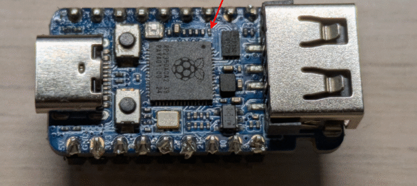
tl;dr: you need to desolder R13, the resistor closest the pin 6 of the board, as indicated by the red arrow in the cover picture of this article
Context
I am currently toying around with emulating a USB device. However, I also wanted to be able to plug a keyboard in, so I needed a second USB port. Since I am not at the stage where I would design my own boards, I only use dev boards.
I found exactly what I needed for my purposes with the RP2350-USB-A:

It is still relatively cheap at ~5 €, features a USB-C port that I can connect to a computer, and a USB-A female connector, which is perfect to connect most keyboards. All I needed was some firmware to run on it and talk to the keyboard. Unfortunately, whatever I did, it never worked.
Fortunately, after learning more about USB and investigating the board and the USB stack, I finally understand what is going on, and how to fix it.
This might be obvious to experts, and the reason known behind closed doors, but other people have stumbled upon the same issue and I found no solution online. There is at least one Reddit thread where /u/arakula says that “none of the examples they provide on their Wiki works” and /u/fullgrid that “It works with mixed success, hotplugging does not work”. This is fully consistent with what I discovered.
Note that this is completely unrelated to the RP2350-E9 errata for the microcontroller. The issue I discuss in this article is specific to the RP2350-USB-A board.
Minimal working example
I reduced the amount of code needed to reproduce the issue to the following. First, I have these environment variables:
export PICO_SDK_PATH=~/opt/pico-sdk
export PICO_BOARD=waveshare_rp2350_usb_a
Then, the project is made out of these files:
tusb_config.h:
#define CFG_TUH_ENABLED 1
#define CFG_TUH_RPI_PIO_USB 1
// only needed for Pico-SDK even if we do not use board_init()
#define BOARD_TUH_RHPORT 0main.c:
#include "pico/stdlib.h"
#include "tusb.h"

void tuh_event_hook_cb(uint8_t rhport, uint32_t eventid, bool inisr) {
    printf("tuh_event_hook_cb(rhport=%d, eventid=%ld, in_isr=%d)\n",
           rhport, eventid, inisr);
}

void tuh_mount_cb(uint8_t addr) {
    printf("Device mounted at address %d\n", addr);
}

int main() {
    stdio_uart_init();
    tuh_init(BOARD_TUH_RHPORT);
    puts("Ready");
    while (1) {
        tuh_task();
        sleep_ms(1);
    }
}CMakeLists.txt:
cmake_minimum_required(VERSION 3.12)
include(pico_sdk_import.cmake)
project(pico_examples C CXX ASM)
add_compile_definitions(PIO_USB_DP_PIN_DEFAULT=12)
pico_sdk_init()

add_executable(main main.c)
target_link_libraries(main pico_stdlib tinyusb_host tinyusb_pico_pio_usb)
# Make sure TinyUSB can find tusb_config.h
target_include_directories(main PUBLIC ${CMAKE_CURRENT_LIST_DIR})

pico_add_extra_outputs(main)
After compiling this project and flashing the resulting binary to the microcontroller, I connected an UART adapter to pins GND, 1 and 2 and was able to observe the following output.
If nothing was connected to the board, when booting (e.g. after pressing reset after flashing), I would get this output:
Ready
tuh_event_hook_cb(rhport=1, eventid=0, in_isr=1)
tuh_event_hook_cb(rhport=0, eventid=2, in_isr=1)
tuh_event_hook_cb(rhport=0, eventid=2, in_isr=1)
tuh_event_hook_cb(rhport=0, eventid=2, in_isr=1)
tuh_event_hook_cb(rhport=0, eventid=2, in_isr=1)
Subsequently plugging the keyboard in would not produce any additional output. However, if I then rebooted the board, with the keyboard still plugged in (e.g. pressing reset again), I would only get:
ReadyAnd not a single tuh_event_hook_cb.
After some investigation, I realized that this behavior was specific to low-speed devices. With full-speed devices, I would get different results. Specifically, if a full-speed device was connected to the board before booting, I would get this when booting:
Ready
tuh_event_hook_cb(rhport=1, eventid=0, in_isr=1)
tuh_event_hook_cb(rhport=0, eventid=2, in_isr=1)
tuh_event_hook_cb(rhport=0, eventid=2, in_isr=1)
tuh_event_hook_cb(rhport=0, eventid=2, in_isr=1)
tuh_event_hook_cb(rhport=0, eventid=2, in_isr=1)
tuh_event_hook_cb(rhport=0, eventid=2, in_isr=1)
tuh_event_hook_cb(rhport=0, eventid=2, in_isr=1)
tuh_event_hook_cb(rhport=0, eventid=2, in_isr=1)
tuh_event_hook_cb(rhport=0, eventid=2, in_isr=1)
tuh_event_hook_cb(rhport=0, eventid=2, in_isr=1)
tuh_event_hook_cb(rhport=0, eventid=2, in_isr=1)
tuh_event_hook_cb(rhport=0, eventid=2, in_isr=1)
tuh_event_hook_cb(rhport=0, eventid=2, in_isr=1)
tuh_event_hook_cb(rhport=0, eventid=2, in_isr=1)
tuh_event_hook_cb(rhport=0, eventid=2, in_isr=1)
tuh_event_hook_cb(rhport=0, eventid=2, in_isr=1)
tuh_event_hook_cb(rhport=0, eventid=2, in_isr=1)
Device mounted at address 1
As you can see, there are more tuh_event_hook_cb and, more importantly, the device is enumerated! Note, however, that hot-plugging would still not work.
Note: To quickly identify whether a device is low-speed of full-speed, just connect it to a Linux computer, and check the output of dmesg. You should see line like this:
[Wed Nov 19 21:18:11 2025] usb 1-4: new low-speed USB device number 45 using xhci_hcdIdentifying the cause
To check that I was using the right GPIO pins to use the USB-A connectors, I looked at the RP2350-USB-A schematics:

At the time, I was using ChatGPT to find new leads and check my own reasoning. However, it did much better this time: it mentioned that the circuit above is meant to be used as a full-speed USB device, not a USB host. Specifically, in the diagram above, we see that the D+ pin of the USB-A port is pulled up to 3.3V by a 1.5 kΩ resistor R13. Note that R10 is not actually soldered in the stock board, as indicated by the “NC” marker.
To understand why this matter, I’ll summarize how USB detects a new device:
- the host keeps D+ and D- at 0V with a weak (15 kΩ) pull-down resistor
- a full-speed device sets D+ to 3.3V with a stronger (1.5 kΩ) pull-up resistor
- the host detects the change in potential on D+

A low-speed device does the same but on D- instead:

Now, when designing the RP2350-USB-A, Waveshare had to make a choice.
- If they pulled up neither D+ or D-, it could never behave as a USB device.
- If they pulled up D+, it could behave as a USB full-speed device, but not as a low-speed device.
- If they pulled up D-, it could behave as a USB low-speed device, but not as a full-speed device.
Between 2 and 3, it makes sense to prefer the more capable mode, so the choice is really between 1 and 2. While 1 completely prevents the board from acting as a USB device, let’s see what happens with 2:
- D+ is always pulled up, so the RP2350-USB-A acting as host will always think there is some USB full-speed device connected to it
- if no device is actually connected to it, it will fail to talk to it, and just give up
- it will not be able to detect a device being hot-plugged, since the level of D+ would not change
- however, if the full-speed device is connected when it starts, everything will just work
- if you connect a low-speed device, D- will also be pulled up, but D+ will also still be up (the device does not pull it down), so the board will see an invalid state and will not talk to the device
In short, when the board is acting as a USB host:
- low-speed devices do not work
- hot-plugging devices do not work
- full-speed devices connected before boot do work!
In other words, option 2 gives slightly more flexibility than option 1, and that probably played a role in the choice made by Waveshare.
Of course, the proper way would have been to make it settable in software, so that the board could properly act as either a host, a full-speed device, or a low-speed device. However, that would have required additional components, and thus extra cost.
Fixing it
Note: With this change, your board won’t be able to act as a device on the USB-A port at all.
I confirmed this with my multimeter set as voltmeter connected to GND and D+. For convenience, I have a small breakout board with a USB-A male connector, but it is not strictly necessary.

I also used the multimeter in continuity testing mode to locate R13. For each resistor (very small black case) on the board, I tested whether either pin had low resistance to 3.3V (0 Ω expected) or to D+ (27 Ω expected). I quickly located our culprit:

You can see a closer look below.

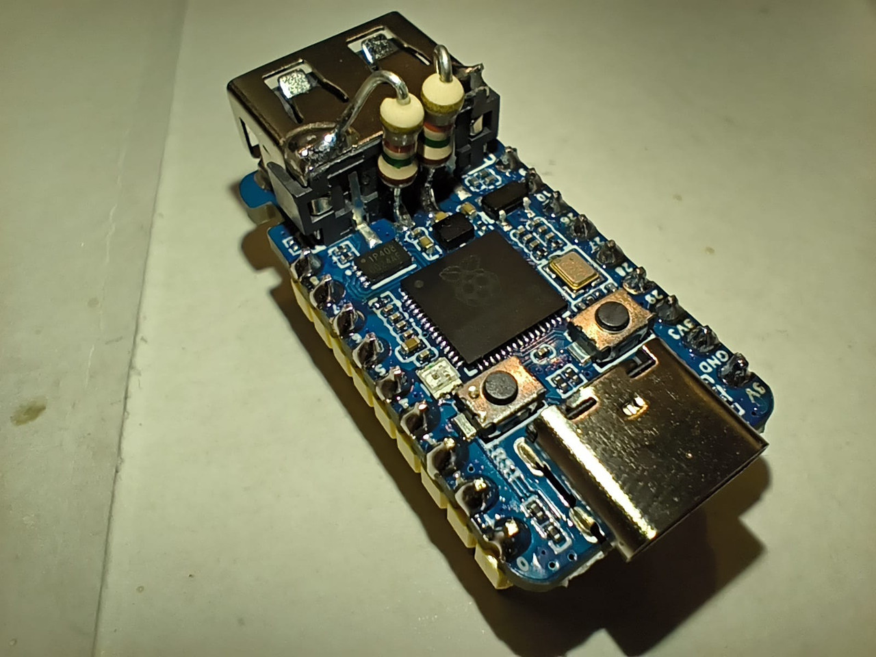
I managed to remove the resistor without damaging the rest of the board too much:

After desoldering R13, and without changing the firmware, I have no trouble anymore when hot-plugging my low-speed keyboard!
Ready
tuh_event_hook_cb(rhport=1, eventid=0, in_isr=1)
tuh_event_hook_cb(rhport=0, eventid=2, in_isr=1)
tuh_event_hook_cb(rhport=0, eventid=2, in_isr=1)
tuh_event_hook_cb(rhport=0, eventid=2, in_isr=1)
tuh_event_hook_cb(rhport=0, eventid=2, in_isr=1)
tuh_event_hook_cb(rhport=0, eventid=2, in_isr=1)
tuh_event_hook_cb(rhport=0, eventid=2, in_isr=1)
tuh_event_hook_cb(rhport=0, eventid=2, in_isr=1)
tuh_event_hook_cb(rhport=0, eventid=2, in_isr=1)
tuh_event_hook_cb(rhport=0, eventid=2, in_isr=1)
tuh_event_hook_cb(rhport=0, eventid=2, in_isr=1)
tuh_event_hook_cb(rhport=0, eventid=2, in_isr=1)
tuh_event_hook_cb(rhport=0, eventid=2, in_isr=1)
tuh_event_hook_cb(rhport=0, eventid=2, in_isr=1)
tuh_event_hook_cb(rhport=0, eventid=2, in_isr=1)
tuh_event_hook_cb(rhport=0, eventid=2, in_isr=1)
tuh_event_hook_cb(rhport=0, eventid=2, in_isr=1)
Device mounted at address 1
Leave a Reply