Context
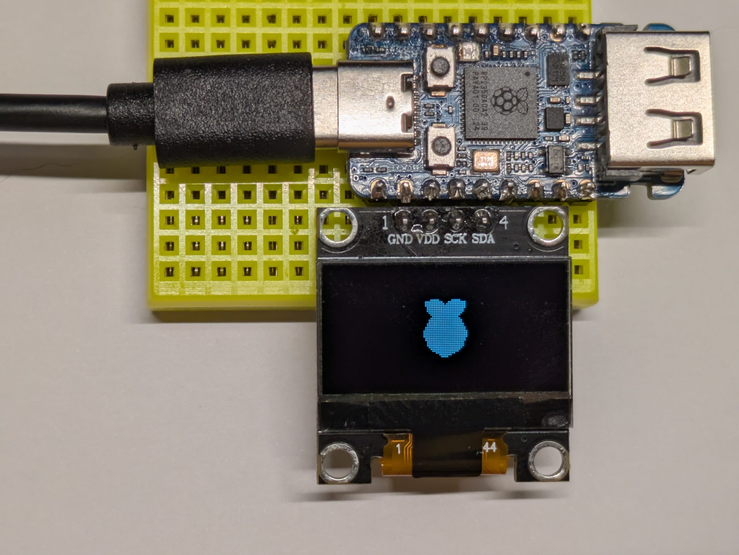
I have a RP2350 and an SSD1306 module. I want to use the former to display stuff on the latter. The most common modules are connected over I²C:

The simple way to use such a display looks like this:
int main(void) {
    // init stuff
    // …

    // main loop
    char buffer[1025]; // 1 byte for command + 1-bit per pixel
    while (1) {
        do_work();
        put_pixel_data_in(buffer);
        update_display();
        buffer[0] = 0x40; // start drawing from line 0
        i2c_write_blocking(i2c_default, SSD1306_I2C_ADDR, buffer, sizeof buffer, false);
    }
}
Basically, to refresh the SSD1306, we need to send an I²C message with a command (first byte) and data (the rest of the buffer). The command 0x40 is “Set Display Start Line”. Specifically, 0x40 means “draw from line 0”, 0x41 means “draw from line 1”, and so on until 0x7F which means “draw from line 63”. Each byte that follows represents 8 pixels of the OLED display.


Now, this works, but it means your program stops completely until the frame is fully sent to the device. How long does it take to send 1025 bytes over I²C? Let’s see how fast the RP2350 and SSD1306 can talk I²C.
Details on the I²C transmission
tl;dr: 26 ms at “400 kHz”, and 11 ms at “1000 kHz”


From this, the RP2350 supports I²C at up to 1000 kHz, but the SSD1306 is only specified up to 400 kHz. However, 1000 kHz can work in good conditions.
However, transmitting 8 bits actually takes 9 cycles. To better understand, this is what the electrical levels actually look like:

The SSD1306 actually contains a detailed version of the exchange:

If you are interested in these details, below is an annotated version of the oscilloscope screenshot from above:

In any case, the point is to show that it takes about 9 cycles to transmit a byte, so 9,225 cycles for the whole buffer, plus about 9 cycles for starting the message. At 400 kHz, this represents 23 ms.
Zooming out a bit:

Here, we can see a full frame (preceded by an almost full frame). Each graduation along the horizontal axis being 5 ms, we can tell that the whole thing lasts about 26 ms, which is actually significantly more than one would expect.
Let’s check the speed of the actual clock signal.

On the screen, we can see 77 cycles of the clock over 11 horizontal graduations. This corresponds to a cycle of 2.86 µs, or 350 kHz. In fact, when using the frequency counter feature of my oscilloscope, I get a measure of 357 kHz. This is consistent with a duration of 26 ms for the full transmission of a frame.
Interestingly, this does not mean we are hitting the limit. When I initialize the I²C for 1000 kHz, I get an actual clock rate of about 800 kHz, or about 11 ms to send a frame.
Busy wait
Now, how can we avoid blocking everything for, at best, 11 ms?
One approach could be to reduce the amount of data transmitted. For instance, instead of updating the whole screen at every refresh, we could just send the parts that changed. However, this requires significant additional logic to keep track of this efficiently, and can add quite a bit of overhead.
But the right question to ask is: why is the CPU waiting for the I²C transmission to complete? Transmitting data, be it UART, I²C, SPI or USB, is normally performed by a dedicated circuit that runs independently of the CPU. In normal circumstances, the CPU is not setting the level of a GPIO pin, sleeping for a bit, then changing the level again (also called “bit-banging”). The role of the CPU is just to feed a buffer that the dedicated circuit will read from.

This is how the datasheet for the RP2350 describes its dedicated circuit for I²C:

From that description, we can see that the I²C controller has a FIFO buffer of 16 bytes. So, this is what actually happens when we transmit the 1,025 bytes of our buffer:
- check if there is room in the FIFO; yes! → push a byte to the I²C FIFO
- check if there is room in the FIFO; yes! → push a byte to the I²C FIFO
- repeat 14 more times
- check if there is room in the FIFO; no! → try again immediately
- check if there is room in the FIFO; no! → try again immediately
- check if there is room in the FIFO; no! → try again immediately
- repeat many times
- check if there is room in the FIFO; yes! → push a byte to the I²C FIFO
- check if there is room in the FIFO; no! → try again immediately
- check if there is room in the FIFO; no! → try again immediately
- check if there is room in the FIFO; no! → try again immediately
- repeat many times
- …
And here is the corresponding code in i2c_write_blocking_internal():
for (byte_ctr = 0; byte_ctr < ilen; ++byte_ctr) {
    bool first = byte_ctr == 0;
    bool last = byte_ctr == ilen - 1;

    if (timeout_check) {
        timeout_check(ts, true); // for per iteration checks, this will reset the timeout
    }

    i2c->hw->data_cmd =
            bool_to_bit(first && i2c->restart_on_next) << I2C_IC_DATA_CMD_RESTART_LSB |
            bool_to_bit(last && !nostop) << I2C_IC_DATA_CMD_STOP_LSB |
            *src++;

    // Wait until the transmission of the address/data from the internal
    // shift register has completed. For this to function correctly, the
    // TX_EMPTY_CTRL flag in IC_CON must be set. The TX_EMPTY_CTRL flag
    // was set in i2c_init.
    do {
        if (timeout_check) {
            timeout = timeout_check(ts, false);
            abort |= timeout;
        }
        tight_loop_contents();
    } while (!timeout && !(i2c->hw->raw_intr_stat & I2C_IC_RAW_INTR_STAT_TX_EMPTY_BITS));

    // If there was a timeout, don't attempt to do anything else.
    if (!timeout) {
        abort_reason = i2c->hw->tx_abrt_source;
        if (abort_reason) {
            // Note clearing the abort flag also clears the reason, and
            // this instance of flag is clear-on-read! Note also the
            // IC_CLR_TX_ABRT register always reads as 0.
            i2c->hw->clr_tx_abrt;
            abort = true;
        }

        if (abort || (last && !nostop)) {
            // If the transaction was aborted or if it completed
            // successfully wait until the STOP condition has occurred.

            // TODO Could there be an abort while waiting for the STOP
            // condition here? If so, additional code would be needed here
            // to take care of the abort.
            do {
                if (timeout_check) {
                    timeout = timeout_check(ts, false);
                    abort |= timeout;
                }
                tight_loop_contents();
            } while (!timeout && !(i2c->hw->raw_intr_stat & I2C_IC_RAW_INTR_STAT_STOP_DET_BITS));

            // If there was a timeout, don't attempt to do anything else.
            if (!timeout) {
                i2c->hw->clr_stop_det;
            }
        }
    }

    // Note the hardware issues a STOP automatically on an abort condition.
    // Note also the hardware clears RX FIFO as well as TX on abort,
    // because we set hwparam IC_AVOID_RX_FIFO_FLUSH_ON_TX_ABRT to 0.
    if (abort)
        break;
}
The important part is the assignment to i2c->hw->data_cmd, which is what populates the sending FIFO buffer. If you want to see how this assignment maps to the hardware, keep going; otherwise, skip to the next section.
From src/rp2_common/hardware_i2c/include/hardware/i2c.h, we can see how the possible values of i2c are defined:
typedef struct i2c_inst i2c_inst_t;

// …
extern i2c_inst_t i2c0_inst;
extern i2c_inst_t i2c1_inst;

#define i2c0 (&i2c0_inst) ///< Identifier for I2C HW Block 0
#define i2c1 (&i2c1_inst) ///< Identifier for I2C HW Block 1

// …

struct i2c_inst {
    i2c_hw_t *hw;
    bool restart_on_next;
};
What we want to see is where the hw field is defined and set. In src/rp2_common/hardware_i2c/i2c.c:
i2c_inst_t i2c0_inst = {i2c0_hw, false};
i2c_inst_t i2c1_inst = {i2c1_hw, false};
Now, we look for i2c_hw_t, i2c0_hw and i2c1_hw. src/rp2040/hardware_structs/include/hardware/structs/i2c.h
typedef struct {
    // …
    _REG_(I2C_IC_DATA_CMD_OFFSET) // I2C_IC_DATA_CMD
    // I2C Rx/Tx Data Buffer and Command Register
    // 0x00000800 [11]    FIRST_DATA_BYTE (0) Indicates the first data byte received after the address...
    // 0x00000400 [10]    RESTART      (0) This bit controls whether a RESTART is issued before the...
    // 0x00000200 [9]     STOP         (0) This bit controls whether a STOP is issued after the...
    // 0x00000100 [8]     CMD          (0) This bit controls whether a read or a write is performed
    // 0x000000ff [7:0]   DAT          (0x00) This register contains the data to be transmitted or...
    io_rw_32 data_cmd;
    // …
} i2c_hw_t;

// …

#define i2c0_hw ((i2c_hw_t *)I2C0_BASE)
#define i2c1_hw ((i2c_hw_t *)I2C1_BASE)
We find I2C0_BASE and I2C1_BASE in src/rp2_common/cmsis/stub/CMSIS/Device/RP2350/Include/RP2350.h:
#define I2C0_BASE                   0x40090000UL
#define I2C1_BASE                   0x40098000UL
The _REG_ macro is actually just an IDE-friendly comment but, nonetheless, the value of I2C_IC_DATA_CMD_OFFSET is found in src/rp2350/hardware_regs/include/hardware/regs/i2c.h:
#define I2C_IC_DATA_CMD_OFFSET _u(0x00000010)Note that I2C_IC_DATA_CMD_OFFSET is not actually used to set the position of the field in the struct. This is simply achieved by the order and size of the previous fields.
In other words, i2c->hw is just a pointer to either the fixed address in memory 0x40090000 or 0x40098000. Writing to i2c->hw->data_cmd writes a further 0x10 bytes from this (0x40090010 or 0x40098010).
And, indeed:


Going async
This was meant to be a short article but, as usual, I went down a few rabbit holes. Now, the point is that the CPU is sending a few bytes down a FIFO buffer, and filling it up as fast as possible. But, at 350 kHz, sending 16 bytes is going to take 411 µs. This is more than enough for the CPU to go and do something else.
Here is a summary of my first draft:
void do_ssd1306_sending(void) {
    if (left_to_send == 0) {
        return;
    }
    // fill the FIFO buffer
    size_t available = i2c_get_write_available(i2c_default);
    if (left_to_send < available) {
        available = left_to_send;
    }
    left_to_send -= available;
    while (available--) {
        i2c_default->hw->data_cmd = *sending++;
    }
}

int main(void) {
    while (1) {
        do_work();
        do_ssd1306_sending();
        if (should_do_new_frame()) {
            put_pixel_data_in(buffer);
            reset_ssd1306_sending();
        }
    }
}
This almost works!
This results in a surprising behavior, where the screen gradually shifts right, a single pixel turns on very briefly at each frame refresh.
The issue is that we never actually end the message. That code still refreshes the display because, after 1024 bytes of data, the SSD1306 driver chip cycles back to the first pixel. However, the next byte that it receives is not supposed to be data, but the 0x40 control byte for the next frame. Since 0x40 contains a single 1 bit, it turns on a single pixel towards the upper left corner of the screen, and proceeds to draw the next 1023 bytes with a 1-pixel shift. When it reaches the last data byte of the second frame, it cycles back to the first pixels, thus immediately erasing the pixel set by 0x40. And so on for every frame refresh.
The missing piece is that we need to indicate the start of messages to the I²C driver. To do this, there are actually some extra bits in the FIFO elements:

Thus, we actually need to send this on the first byte:
i2c_default->hw->data_cmd = (1 << I2C_IC_DATA_CMD_RESTART_LSB) | 0x40;Where I2C_IC_DATA_CMD_RESTART_LSB is just defined as 10 in src/rp2350/hardware_regs/include/hardware/regs/i2c.h. And this is exactly what i2c_write_blocking_internal() does!
Summary
We have changed the main loop slightly to call do_ssd1306_sending() regularly, which will gradually feed the I²C controller as needed. This does make transmission happen faster, but allows the CPU to do other things while this happens. Note that TinyUSB does something very similar with its tud_task() and tuh_task().
In some cases, feeding the bytes one by one can take a significant amount of CPU time. In such scenarios, a more advanced approach is used, where the controller directly reads from memory without waiting for the CPU to feed it. This is DMA. However, this is overkill for many usages, and I will probably not need anything more than properly using the FIFO.

Leave a Reply