- How to use “real” UART
- Arduino’s Automatic Reset
- Linux always toggles DTR & RTS
- Espressif’s Automatic Reset
- Talking to Espressif’s Bootloader
- The ESP32-S2 reset pin
- Reproducing Espressif’s reset circuit
- The missing part of Espressif’s reset circuit
- Transistors in reverse and redundant circuits
- The serial TX path seems to be down
I recently went into a deep dive on “UART” and will publish a much longer article on the topic. This is just a recap of the basics to help put things in context. Many tutorials focus on using UART over USB, which adds many layers of abstraction, hiding what it actually is. Here, I deliberately use an external adapter to make things more real.
Nowadays, you typically use UART to talk to a microcontroller (the brains of an embedded device). The microcontroller chip alone cannot do much, so you will want a devkit board. Many options exist, but I am using the ESP32-S2-Saola-1RI (~18 €), because I am interested in working with the ESP32-S2 microcontroller, and because it exposes the UART pins in a convenient manner.

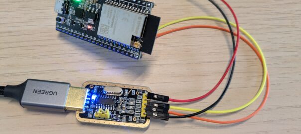
The simplest way to use UART is to connect it to your computer, and you would do that with a UART-to-USB adapter. I am using a CH340G-2 (~2 €). These usually come with “jumper wires”, which you will need to connect the adapter to the microcontroller board.


We connect GND to GND, 5V to 5V, TX to RX, and RX to TX. In this case, the pins are labelled directly on the microcontroller board. But you usually have to check the pin layout in the documentation (or “datasheet”).

When I plug the adapter into my computer, various LEDs light up:
- a blue LED on the adapter informs me that it is powered;
- a red LED on the microcontroller board informs me that it is powered as well;
- an RGB LED slowly cycles through green, red and blue (green in the picture below); this is the default program loaded on the board, a kind of “Hello, World”.

To see what the microcontroller is sending through UART, we first need to find the name that the computer assigned to it (“device” or “port”).
On Linux, it usually shows up as /dev/ttyUSB0, but it might vary a bit (e.g. /dev/ttyUSB1, /dev/ttyACM0). To be sure, run sudo dmesg. You should see some lines like the ones below after plugging the UART-to-USB adapter. The last line in the example is telling you that the device you should use is /dev/ttyUSB0.
[242043.322844] usb 1-4: new full-speed USB device number 26 using xhci_hcd
[242043.636252] usb 1-4: New USB device found, idVendor=1a86, idProduct=7523, bcdDevice= 2.64
[242043.636257] usb 1-4: New USB device strings: Mfr=0, Product=2, SerialNumber=0
[242043.636259] usb 1-4: Product: USB Serial
[242043.661138] ch341 1-4:1.0: ch341-uart converter detected
[242043.674990] usb 1-4: ch341-uart converter now attached to ttyUSB0
On macOS, the device will usually appear as /dev/tty.usbserial-* or /dev/tty.usbmodem-* where * will depend on the specific device. On Windows, it will be COM1, or COM2, etc.
On all three, you can use PuTTY as the UART client. First, in the main screen, switch the Connection type: to Serial, then put the name of the device in the text field under Serial line. For Speed, you will have to check the default baud rate of the microcontroller. In my case, this is 115200, which is the most frequent one, although 57600 is also common.
Note: On Linux, you might need to run the UART client as sudo. If you want to avoid that, look into adding udev rules and/or adding your user to the dialout group (note that you need to log out and in again after adding your user to a new group).

After clicking Open, I can see text being sent from the microcontroller periodically. Note that this might be different if you are using a different microcontroller, or if the manufacturer of the board flashed it with a different firmware.

However, this is not the most impressive thing about UART. As someone used to working with PCs rather than embedded systems, I expect to wait several seconds after boot before getting anything on the screen. With UART, you can get feedback from the microcontroller from the first millisecond!
To observe this, just press the “RST” button on the board while your UART client is running. Here is the output I get when looking at the UART output with tio when the microcontroller boots.
$ tio -b 115200 /dev/ttyUSB0
[14:49:08.505] tio 3.8
[14:49:08.505] Press ctrl-t q to quit
[14:49:08.515] Connected to /dev/ttyUSB0
ESP-ROM:esp32s2-rc4-20191025
Build:Oct 25 2019
rst:0x1 (POWERON),boot:0x8 (SPI_FAST_FLASH_BOOT)
SPIWP:0xee
mode:DIO, clock div:2
load:0x3ffe8100,len:0x4
load:0x3ffe8104,len:0x18f0
load:0x40050000,len:0x1678
load:0x40054000,len:0x2100
entry 0x40050334
I (49) boot: ESP-IDF v4.2-dev-461-g6fd4904-dirty 2nd stage bootloader
I (49) boot: compile time 17:09:57
I (49) boot: chip revision: 0
I (52) boot.esp32s2: SPI Speed      : 40MHz
I (57) boot.esp32s2: SPI Mode       : DIO
I (62) boot.esp32s2: SPI Flash Size : 2MB
I (66) boot: Enabling RNG early entropy source...
I (72) boot: Partition Table:
I (75) boot: ## Label            Usage          Type ST Offset   Length
I (83) boot:  0 nvs              WiFi data        01 02 00009000 00006000
I (90) boot:  1 phy_init         RF data          01 01 0000f000 00001000
I (98) boot:  2 factory          factory app      00 00 00010000 00100000
I (105) boot: End of partition table
I (109) esp_image: segment 0: paddr=0x00010020 vaddr=0x3f000020 size=0x05454 ( 21588) map
I (124) esp_image: segment 1: paddr=0x0001547c vaddr=0x3ffbd740 size=0x01c2c (  7212) load
I (129) esp_image: segment 2: paddr=0x000170b0 vaddr=0x40024000 size=0x00404 (  1028) load
I (136) esp_image: segment 3: paddr=0x000174bc vaddr=0x40024404 size=0x08b5c ( 35676) load
I (157) esp_image: segment 4: paddr=0x00020020 vaddr=0x40080020 size=0x139a8 ( 80296) map
I (179) esp_image: segment 5: paddr=0x000339d0 vaddr=0x4002cf60 size=0x007d4 (  2004) load
I (186) boot: Loaded app from partition at offset 0x10000
I (186) boot: Disabling RNG early entropy source...
I (188) cache: Instruction cache 	: size 8KB, 4Ways, cache line size 32Byte
I (196) cpu_start: Pro cpu up.
I (199) cpu_start: Single core mode
I (204) heap_init: Initializing. RAM available for dynamic allocation:
I (211) heap_init: At 3FFBD734 len 0000000C (0 KiB): D/IRAM
I (217) heap_init: At 3FFBFB28 len 0003C4D8 (241 KiB): D/IRAM
I (223) heap_init: At 3FFFC000 len 00003A10 (14 KiB): DRAM
I (230) cpu_start: Pro cpu start user code
I (287) spi_flash: detected chip: generic
I (288) spi_flash: flash io: dio
W (288) spi_flash: Detected size(4096k) larger than the size in the binary image header(2048k). Using the size in the binary image header.
I (298) cpu_start: Starting scheduler on PRO CPU.
I (304) example: esp32s2 IDF_test version: 1.01
I (304) example: esp_idf version:8.2.0
I (314) example: LED Rainbow Chase  Start in GPIO 18
red...
blue...
red...
green...
blue...
I could not find the exact source code for the firmware that is running on it, but it is based on an example from the esp-idf repository. Here, text is sent to UART by using the ESP_LOGI macro:
ESP_LOGI(TAG, "LED Rainbow Chase Start"); // TAG == "example"This relies on Espressif’s development framework, named ESP-IDF. When using other microcontrollers, other frameworks or other languages, you might have to do things differently.
And that’s all for today!

Leave a Reply