- How to use “real” UART
- Arduino’s Automatic Reset
- Linux always toggles DTR & RTS
- Espressif’s Automatic Reset
- Talking to Espressif’s Bootloader
- The ESP32-S2 reset pin
- Reproducing Espressif’s reset circuit
- The missing part of Espressif’s reset circuit
- Transistors in reverse and redundant circuits
- The serial TX path seems to be down
As mentioned in my previous article, I am planning to publish a long-form article on UART. I am doing a series of shorter articles to lay the groundwork. This is one of these “short” articles; this one about how Arduino uses UART. Of course, I still went way too deep in this topic for something that was meant to be a short segue. Anyway, on to the actual content!
I have an Arduino Leonardo. It features an ATmega32U4 microcontroller, which can do USB directly. This is great, but I actually want to play around with “real” UART. It so happens that the older Arduino Uno does “real” UART, so I got a cheap clone from AliExpress for less than 4€. Its design looks somewhat similar to the Arduino Uno R3 SMD.

“Arduino” Uno
This section is not necessary to follow the rest of the explanations.
Since this is a clone, I thought it would be useful to take a look at how similar it really is to the original. There are some significant differences, but they should not matter for the casual user.
The Arduino Uno is built around the ATmega328P microcontroller. This clone uses the same chip, as using a different microcontroller would be a huge difference with the original, making this board not really a clone.

However, the original Arduino Uno actually features a second microcontroller. Depending on revisions, that would be the ATmega8U2 or the ATmega16U2. The Arduino Uno uses it as a UART-to-USB adapter (with the proper firmware). This is surprising, since there are dedicated chips for that, but the actual reason is to avoid needing a custom driver:
“Which is when we realized there was this thing called CDC (communications device class) protocol, which was embedded into operating systems. It’s the reason you don’t need a driver for a USB serial port. We found that you could develop a firmware for some simple Atmel processors that worked just the same as FTDI chips, but would liberate us from needing a driver.” (source)
USB CDC is the standard way to expose a UART-like interface through USB. Since it is part of the core specification of USB, it should work out-of-the-box on any operating system with proper USB support. However, dedicated UART-to-USB adapter chips were designed without USB CDC and instead require some specific software (a “driver”) to be installed by the user to work.
Nowadays, I would expect the drivers to be installed automatically, but it was definitely not the case at the time the Arduino Uno was designed. So, to make things simpler for users, they used a microcontroller and wrote a firmware to make it talk USB CDC.
The clone has replaced it with a dedicated UART-to-USB adapter (a CH340G). Also note that, while the Arduino Uno has two ICSP connectors, one to program the ATmega328P, and one to program the ATmega8U2/ATmega16U2, this clone has a single ICSP connector.

Edit: I checked with high-magnification glasses that I again got from AliExpress for 14 €, and there is really nothing written there.
“Real” UART on the Uno
Like before, we connect GND to GND, TX to RX and RX to TX. We’ll also power the board by connecting VCC to 5V. They are conveniently labelled on the board, so this is quite easy.


Unfortunately, the firmware which is shipped with this board does not send anything through UART. We could write some firmware and upload it, using AVRDUDE. But that process itself uses UART, so we’ll just use that as an example.
Let’s try running a basic command to request information on the target microcontroller.
$ avrdude -p atmega328p -c arduino -P /dev/ttyUSB0 -b 115200 -n -v

avrdude: Version 7.1
         Copyright the AVRDUDE authors;
         see https://github.com/avrdudes/avrdude/blob/main/AUTHORS

         System wide configuration file is /etc/avrdude.conf
         User configuration file is /home/qsantos/.avrduderc
         User configuration file does not exist or is not a regular file, skipping

         Using Port                    : /dev/ttyUSB0
         Using Programmer              : arduino
         Overriding Baud Rate          : 115200
avrdude stk500_recv() error: programmer is not responding
avrdude stk500_getsync() warning: attempt 1 of 10: not in sync: resp=0x00
avrdude stk500_recv() error: programmer is not responding
avrdude stk500_getsync() warning: attempt 2 of 10: not in sync: resp=0x00
avrdude stk500_recv() error: programmer is not responding
avrdude stk500_getsync() warning: attempt 3 of 10: not in sync: resp=0x00
avrdude stk500_recv() error: programmer is not responding
avrdude stk500_getsync() warning: attempt 4 of 10: not in sync: resp=0x00
avrdude stk500_recv() error: programmer is not responding
avrdude stk500_getsync() warning: attempt 5 of 10: not in sync: resp=0x00
avrdude stk500_recv() error: programmer is not responding
avrdude stk500_getsync() warning: attempt 6 of 10: not in sync: resp=0x00
avrdude stk500_recv() error: programmer is not responding
avrdude stk500_getsync() warning: attempt 7 of 10: not in sync: resp=0x00
avrdude stk500_recv() error: programmer is not responding
avrdude stk500_getsync() warning: attempt 8 of 10: not in sync: resp=0x00
avrdude stk500_recv() error: programmer is not responding
avrdude stk500_getsync() warning: attempt 9 of 10: not in sync: resp=0x00
avrdude stk500_recv() error: programmer is not responding
avrdude stk500_getsync() warning: attempt 10 of 10: not in sync: resp=0x00
avrdude main() error: unable to open programmer arduino on port /dev/ttyUSB0

avrdude done.  Thank you.
This fails. The reason is that the board is currently running some user firmware (in my case, that just makes the “L” LED blink slowly), which does not understand AVRDUDE. There is a short period where the microcontroller is able to understand AVRDUDE: right after it starts.
Note: There is no magic. The thing that makes the microcontroller understand AVRDUDE is just another firmware called the “bootloader”. The microcontroller loads that bootloader first. The bootloader listens for commands from UART for a short while and, if no commands are received, it just starts the user firmware from flash memory.
We need to press the reset button (the only button on the board, next to the USB-B port) right before running AVRDUDE. When we do so, we get a proper report:
$ avrdude -p atmega328p -c arduino -P /dev/ttyUSB0 -b 115200 -n -v

avrdude: Version 7.1
         Copyright the AVRDUDE authors;
         see https://github.com/avrdudes/avrdude/blob/main/AUTHORS

         System wide configuration file is /etc/avrdude.conf
         User configuration file is /home/qsantos/.avrduderc
         User configuration file does not exist or is not a regular file, skipping

         Using Port                    : /dev/ttyUSB0
         Using Programmer              : arduino
         Overriding Baud Rate          : 115200
         AVR Part                      : ATmega328P
         Chip Erase delay              : 9000 us
         PAGEL                         : PD7
         BS2                           : PC2
         RESET disposition             : possible i/o
         RETRY pulse                   : SCK
         Serial program mode           : yes
         Parallel program mode         : yes
         Timeout                       : 200
         StabDelay                     : 100
         CmdexeDelay                   : 25
         SyncLoops                     : 32
         PollIndex                     : 3
         PollValue                     : 0x53
         Memory Detail                 :

                                           Block Poll               Page                       Polled
           Memory Type Alias    Mode Delay Size  Indx Paged  Size   Size #Pages MinW  MaxW   ReadBack
           ----------- -------- ---- ----- ----- ---- ------ ------ ---- ------ ----- ----- ---------
           eeprom                 65    20     4    0 no       1024    4      0  3600  3600 0xff 0xff
           flash                  65     6   128    0 yes     32768  128    256  4500  4500 0xff 0xff
           lfuse                   0     0     0    0 no          1    1      0  4500  4500 0x00 0x00
           hfuse                   0     0     0    0 no          1    1      0  4500  4500 0x00 0x00
           efuse                   0     0     0    0 no          1    1      0  4500  4500 0x00 0x00
           lock                    0     0     0    0 no          1    1      0  4500  4500 0x00 0x00
           signature               0     0     0    0 no          3    1      0     0     0 0x00 0x00
           calibration             0     0     0    0 no          1    1      0     0     0 0x00 0x00

         Programmer Type : Arduino
         Description     : Arduino for bootloader using STK500 v1 protocol
         Hardware Version: 3
         Firmware Version: 4.4

avrdude: AVR device initialized and ready to accept instructions
avrdude: device signature = 0x1e950f (probably m328p)

avrdude done.  Thank you.
It works! This is what you had to do for the earliest boards from Arduino, but they quickly improved the process so that the user would not have to fiddle with the reset button to upload a firmware.
Automatic reset with “real” UART
“It turned out that if you put a capacitor between the reset pin of the microcontroller and one of the serial port pins,” he explains, “it would reset the board automatically whenever you opened the port.” This small tweak became a vital and very popular aspect of the UNO’s useability. (source)
Depending on your background, this sounds either obvious or completely opaque over multiple levels. I was in the latter camp until very recently.
The first thing you need to understand this is that, in addition to GND, TX and RX, UART1 defines a number of additional pins. Although they are obsolete, they are still supported. In particular, DTR and RTS will have a very predictable behavior:
- By default, they will be electrically high (e.g. at 3.3V)
- When the UART device gets opened, they are automatically set to electrically low (0V)
This happens, for instance, when AVRDUDE opens /dev/ttyUSB0 to send a firmware to the board. All we need to do is to make it so that the board resets when DTR or RTS flips to low.
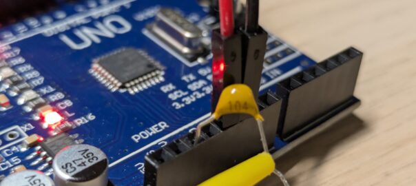
Let’s try connecting DTR to the RES (reset) of the board.

Unfortunately, this does not work. This brings us to:
The second thing you need to understand is that the “RESET” pin really is a “keep running” pin. If you use it, the microcontroller will turn off when it is low (e.g. 0V), and turn on when it is high (e.g. 3.3V). So, we are successfully turning the microcontroller off, but it never starts again.
The third thing to understand is that a capacitor is the perfect solution for that. In short, it lets the current flow through it for a short time, until it gets full. So, if we put a capacitor between DTR and RES, when DTR goes from electrically high to low, this will make RES low for just a short duration.
You can visualize this with the CircuitJS1 simulation below. The graph on the left shows the electrical level of DTR. The graph on the right shows the electrical level of RES. You can toggle the electrical level of DTR by clicking on the switch and observe the effect on RES. It should drop to low immediately, but very quickly returns to high.
Note: The simulation includes a few additional components that are included in the board, but only the 10 kΩ resistor is really needed to make it work at all.
We will need a capacitor with a high enough value that the RES pin is set to a low electrical value long enough for the microcontroller to notice. The recommendation is to use a 100 nF capacitor, but even 10 nF seems to work. Anything lower, and the microcontroller does not reset.


With this setup, no physical action is required when running AVRDUDE! The microcontroller resets automatically right when needed.
Automatic reset over USB
The same principle is used when programming the Arduino Uno through USB. After all, the ATMega16U2 is just a bridge between USB (CDC) and the physical UART communication line.
The schematics of the Arduino Uno can be confusing. I want to focus on the resetting of the microcontroller, so I removed everything else:

The first thing is that this is connected to the pin 13 of the ATmega16U2, which is labelled “CTS”, even though it is supposed to be DTR. The thing to remember is that this chip is a microcontroller, not an UART adapter, and this pin can be used for any purpose (this is a GPIO pin). Arduino just decided to write the firmware for this chip to output DTR on this pin.
The Arduino Uno lets you disable the auto-reset feature, by scraping away the solder between the pads labelled “RST EN”. The two pads are labelled “1” and “2” in the schematics, and a wire shorts them to indicate that they are connected by default. This can be confusing, but the software used to produce the schematics does not have a way to indicate that the pads are soldered together. Instead, this is indicated with an extra wire around the pads.

We then have a 10kΩ resistor labelled “RN1D”. It serves the same purpose as the resistor I have used in the EveryCircuit diagram above. When the capacitor is “blocking” (and when nothing is connected to the RES pin of the board), this resistor ensures that the level of “RESET” is 5V. The 10kΩ value is high enough that the capacitor (or the RES pin of the board) can “override” it easily and set “RESET” to ~0V.
The diode is there to handle the case when the capacitor discharges. Without this diode, when DTR switches from electrically low to high, the charge in the capacitor will cause a suddent voltage spike way above 5V. The diode prevents the voltage from even rising above 5V. This is a shunt diode2.
The other resistor, 1kΩ and labelled “RN2D” sets the “default” voltage of DTR to 0V. This avoids random oscillations when the ATmega16u2 is starting and the GPIO PD7 pin is still floating, which could cause unwanted resets. This can also avoid current flowing back into the microcontroller.
“TP_DTR” is a “test point”: a physical place on the board where you can measure the voltage to check that everything works as expected.
Considering all this, we can see that this is nothing more than what we did with the capacitor earlier.
Conclusion
This is a relatively unimportant feature of the Arduino Uno. However, to properly understand it, I needed to uncover a significant amount of implicit knowledge that is absolutely not obvious for someone like me, who mostly ever dealt with software.
- Strictly speaking, this is RS-232 which defines this, but let’s keep that aside for now. ↩︎
- Combined with the capacitor and the resistor, it looks like a negative biased clamper with negative bias. ↩︎

Leave a Reply