- How to use “real” UART
- Arduino’s Automatic Reset
- Linux always toggles DTR & RTS
- Espressif’s Automatic Reset
- Talking to Espressif’s Bootloader
- The ESP32-S2 reset pin
- Reproducing Espressif’s reset circuit
- The missing part of Espressif’s reset circuit
- Transistors in reverse and redundant circuits
- The serial TX path seems to be down
RST defaults to high
This is an addendum to the article about Espressif’s automatic reset. In that article, we observed the effect of the RST pin on the ESP32-S2-Saola-1RI board:
- if nothing is connected to RST, it runs normally
- if something sets the electrical level of RST to low (0V), the board does not run
- if something sets the electrical level of RST to high (3.3V), the board runs
I skipped over this topic quickly, so I am now taking the time to explain how the RST pin manages to have a defined behavior when nothing is connected to it, while allowing external control when something is connected to it.
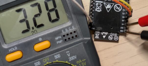
First, we can see that the RST pin is indeed electrically high when nothing is connected to it by using a voltmeter.

CHIP_PU
Now, let’s see what this RST pin is connected to. For this, we look at the schematics of the board and find the description of the “pin headers”:


The RST pin is next to the pin labelled “46” on the board. In the schematics, next to GPIO46, we see CHIP_PU, which is an internal label that stands for “Chip Power-Up”. We can find that label in a couple more places.

This is where CHIP_PU is connected to the automatic reset circuit we explored in the previous article. R28 and R29 are 0Ω resistor, behaving just like wires. The reason they exist is that they are actually component on the board, that a user can choose to unsolder, to break the path, and thus disable the automatic reset.
In this article, we’ll assume that no UART adapter is connected.

This is the physical reset button on the board. Contacts 1 and 2 are connected together, and so are contacts 3 and 4. When the button is pressed, they all become connected together, connecting CHIP_PU to ground directly, thus forcing it electrically low.
The pull-up resistor
Onto the next occurrence of CHIP_PU:

This is where the magic happens. The circuit can look slightly confusing, with the inclusion of the GPIO18 pin, but it is best to think of both halves as separate circuits, that just happen to both use VDD33 (3.3V rail). If we focus on the right half, we see that CHIP_PU is connected through a resistor to VDD33.
If nothing else is connected to CHIP_PU, its electrical level will thus be that of VDD33, i.e. 3.3V. Of course, the chip is connected to CHIP_PU to read its level, but it will use a special circuit to avoid changing its electrical level while doing so.
Now, if you connect, say, the DTR pin of a UART adapter to RST, you will have two cases. First, if RST is electrically high at 3.3V, or “de-asserted”, CHIP_PU will unsurprisingly be at 3.3V. However, if RST is electrically low at 0V, or “asserted”, you will end up with something like this:

Here, Vin would be VDD33 and Vout would be CHIP_PU. In that situation, the electrical level of Vout / CHIP_PU will depend on the values of the resistors:

Here R1 is 10kΩ and R2 would be much smaller (e.g. 0Ω), resulting in Vout / CHIP_PU to also be very small (e.g. 0V).
This design lets CHIP_PU have a “default” electrical level at 3.3V that can be overridden by an external pin. We say that R36 is a pull-up resistor, because it “pulls” the electrical level of CHIP_PU towards the high level.
The module
The last occurrence of CHIP_PU connects it to the EN pin of the ESP32-S2 module:

“EN” is short for “ENable”; as in, when it is electrically high, the microcontroller is enabled.
My devkit features a ESP32-S2-WROVER-1. Looking at the schematics at page 20 of its datasheet, we can see the module’s CHIP_PU is connected to the ESP32-S2’s pin 56, also labelled CHIP_PU:

Finally, from the documentation of the ESP32-S2 microcontroller itself:

The note is telling us that the electrical level of CHIP_PU should not be left to random chance, but should be actively controlled. This is precisely what the pull-up resistor does.
The capacitors
As an extra section to this addendum to the side article to the main UART article (that I will write one day if I manage to close all loose ends), I wanted to look closer at two components connected to CHIP_PU that I ignored so far.
In the schematics above, you might have noticed C20, a 0.1µF capacitor next to the reset switch, and C22, a 1µF capacitor next to the pull-up resistor. So, what are capacitors used for?
In short, a capacitor acts somewhat like an open-circuit at low frequencies (the capacitor quickly approaches full charge and reduces current), and somewhat like a short-circuit at high frequencies (the capacitor barely charges before the current reverses direction). The higher the capacitance, the lower the frequency that can pass through. At the extreme, a capacitor of infinite capacitance is just a wire and would let through even DC (direct current, 0 Hz) and a capacitor of zero capacitance is just a gap in the circuit, letting nothing through.


In the case of C22, the 1µF capacitor, combined with a 10kΩ resistor, the cutoff frequency will be about 16 Hz. This avoids higher frequencies (such as variations due to the 60 Hz of the electricity grid, or other activities on the board) from resetting the chip, while allowing slow frequencies (such as pressing the reset button, or toggling UART’s DTR for 0.1s) to do so.
C20, the 0.1µF, capacitor, is actually optional. In fact its label is colored in green with a “(NC)” suffix, meaning “Not connected”. That is, there are pads and room for the capacitor, but it is not actually present on the board. To check, we search for “C20” in the PCB diagram:

Using this, we can look for C20 on the actual board, next to the RST switch.

In any case, the purpose of this optional capacitor is to be physically much closer to the switch, in case C22 is too far away to effectively debounce when the switch is being operated. If C20 were also 1µF, the combination of C20 and C22 would provide a capacitance of 2µF, meaning the cut-off frequency would be 8 Hz, which is starting to get uncomfortably low. 0.1µF is enough for debouncing, so this is what is suggested.

Leave a Reply