- How to use “real” UART
- Arduino’s Automatic Reset
- Linux always toggles DTR & RTS
- Espressif’s Automatic Reset
- Talking to Espressif’s Bootloader
- The ESP32-S2 reset pin
- Reproducing Espressif’s reset circuit
- The missing part of Espressif’s reset circuit
- Transistors in reverse and redundant circuits
- The serial TX path seems to be down
In previous articles, we saw how to use “real” UART, and looked into the trick used by Arduino to automatically reset boards when uploading firmware. Today, we’ll look into how Espressif does something similar, using even more tricks.
“Real” UART on the Saola
As usual, let’s first simply connect the UART adapter. Again, we connect GND to GND, TX to RX and RX to TX. I also choose to power the board using the VCC pin of the UART adapter, but you can power it from USB instead.


Note: There is no widespread convention for the wires between TX and RX. However, choosing one makes it simpler to connect wires without having to check which is which every five seconds. Lately, I have taken the habit of using orange for TX on the adapter (and RX on the target), and yellow for RX on the adapter (and TX on the target).
In any case, when we plug the UART adapter with an USB cable, the target device (ESP32-S2-Saola-1RI here) should start running.

In a serial client, we can again see:
$ tio -b 115200 /dev/ttyUSB0
blue...
red...
green...
blue...
Now, for the new part!
Automatic Reset with “real” UART
In the Arduino article, we exploited the fact that DTR and RTS pins change from being electrically high to electrically low when a program opens the associated serial device. Let’s do something similar and connect the DTR pin of the UART adapter to the RST pin of the Espressif board.

Note that I did not put a capacitor between DTR and RST. This is intentional. It does mean that, if we just open the serial device (with, e.g., tio), the target board stops running. But we’ll address that a different way: we are going to control the level of these pins manually1.
First, we can check the status of these pins in tio, by hitting Ctrl+t, and then uppercase L. tio should produce an output like the one below.
$ tio -b 115200 /dev/ttyUSB0
[18:04:22.277] tio 3.8
[18:04:22.277] Press ctrl-t q to quit
[18:04:22.279] Connected to /dev/ttyUSB0
(I press Ctrl+t, release it, then press Shift+l)
[18:04:35.055] Line states:
[18:04:35.055]  DTR: LOW
[18:04:35.055]  RTS: LOW
[18:04:35.055]  CTS: HIGH
[18:04:35.055]  DSR: HIGH
[18:04:35.055]  DCD: HIGH
[18:04:35.055]  RI : HIGH
We can see that both DTR and RTS are electrically low, as expected. We can switch the value of DTR by hitting Ctrl+t, and then lowercase g:
(I press Ctrl+t, release it, then press g)
[18:04:50.979] Please enter which serial line number to toggle:
[18:04:50.979] (0) DTR
[18:04:50.979] (1) RTS
[18:04:50.979] (2) CTS
[18:04:50.979] (3) DSR
[18:04:50.979] (4) DCD
[18:04:50.979] (5) RI
(I press 0)
[18:04:56.144] Setting DTR to HIGH
ESP-ROM:esp32s2-rc4-20191025
Build:Oct 25 2019
rst:0x1 (POWERON),boot:0x8 (SPI_FAST_FLASH_BOOT)
SPIWP:0xee
mode:DIO, clock div:2
load:0x3ffe8100,len:0x4
load:0x3ffe8104,len:0x18f0
load:0x40050000,len:0x1678
load:0x40054000,len:0x2100
entry 0x40050334
I (49) boot: ESP-IDF v4.2-dev-461-g6fd4904-dirty 2nd stage bootloader
I (49) boot: compile time 17:09:57
I (49) boot: chip revision: 0
I (52) boot.esp32s2: SPI Speed      : 40MHz
I (57) boot.esp32s2: SPI Mode       : DIO
I (62) boot.esp32s2: SPI Flash Size : 2MB
I (66) boot: Enabling RNG early entropy source...
I (72) boot: Partition Table:
I (75) boot: ## Label            Usage          Type ST Offset   Length
I (83) boot:  0 nvs              WiFi data        01 02 00009000 00006000
I (90) boot:  1 phy_init         RF data          01 01 0000f000 00001000
I (98) boot:  2 factory          factory app      00 00 00010000 00100000
I (105) boot: End of partition table
I (109) esp_image: segment 0: paddr=0x00010020 vaddr=0x3f000020 size=0x05454 ( 21588) map
I (124) esp_image: segment 1: paddr=0x0001547c vaddr=0x3ffbd740 size=0x01c2c (  7212) load
I (129) esp_image: segment 2: paddr=0x000170b0 vaddr=0x40024000 size=0x00404 (  1028) load
I (136) esp_image: segment 3: paddr=0x000174bc vaddr=0x40024404 size=0x08b5c ( 35676) load
I (157) esp_image: segment 4: paddr=0x00020020 vaddr=0x40080020 size=0x139a8 ( 80296) map
I (179) esp_image: segment 5: paddr=0x000339d0 vaddr=0x4002cf60 size=0x007d4 (  2004) load
I (186) boot: Loaded app from partition at offset 0x10000
I (186) boot: Disabling RNG early entropy source...
I (188) cache: Instruction cache 	: size 8KB, 4Ways, cache line size 32Byte
I (196) cpu_start: Pro cpu up.
I (199) cpu_start: Single core mode
I (204) heap_init: Initializing. RAM available for dynamic allocation:
I (211) heap_init: At 3FFBD734 len 0000000C (0 KiB): D/IRAM
I (217) heap_init: At 3FFBFB28 len 0003C4D8 (241 KiB): D/IRAM
I (223) heap_init: At 3FFFC000 len 00003A10 (14 KiB): DRAM
I (230) cpu_start: Pro cpu start user code
I (287) spi_flash: detected chip: generic
I (288) spi_flash: flash io: dio
W (288) spi_flash: Detected size(4096k) larger than the size in the binary image header(2048k). Using the size in the binary image header.
I (298) cpu_start: Starting scheduler on PRO CPU.
I (304) example: esp32s2 IDF_test version: 1.01
I (304) example: esp_idf version:8.2.0
I (314) example: LED Rainbow Chase  Start in GPIO 18
red...
green...
blue...
red...
green...
blue...
By controlling the level of DTR, we can reset the target board from software!
Bootloader mode
In the case of Arduino, to upload a new firmware to the microcontroller, you just need to reset it and send commands quickly after. This has the merit of being simple, but this means:
- There is a delay when the microcontroller starts, where it checks for any commands to upload firmware. This can be unwanted for a final product.
- The software used to upload the firmware (AVRDUDE) must have the right timing with the reset. This can make it harder to handle in some cases. For instance, when resetting manually.
Espressif went a different way when it comes to firmware upload. Instead of having a sequence where the bootloader runs, then the user code runs, Espressif chips will boot in either mode. Selecting the boot mode is done by controlling the electrical level of the GPIO0 pin.

Let’s use the UART’s RTS to control the electrical level of GPIO0. For this, we need an additional cable.

First, let’s check that we can still boot it in normal mode. For this, we must ensure that GPIO0 is at a high electrical level. Since RTS is automatically set to a low electrical level when we open the serial device with tio, we must toggle it first.
$ tio -b 115200 /dev/ttyUSB0
[18:21:26.005] tio 3.8
[18:21:26.005] Press ctrl-t q to quit
[18:21:26.006] Connected to /dev/ttyUSB0
(I press Ctrl+t, release it, then press Shift+l)
[18:21:28.175] Line states:
[18:21:28.175]  DTR: LOW
[18:21:28.175]  RTS: LOW
[18:21:28.175]  CTS: HIGH
[18:21:28.175]  DSR: HIGH
[18:21:28.175]  DCD: HIGH
[18:21:28.175]  RI : HIGH
(I press Ctrl+t, release it, then press g)
[18:21:32.135] Please enter which serial line number to toggle:
[18:21:32.135] (0) DTR
[18:21:32.135] (1) RTS
[18:21:32.135] (2) CTS
[18:21:32.135] (3) DSR
[18:21:32.135] (4) DCD
[18:21:32.135] (5) RI
(I press 1)
[18:21:33.061] Setting RTS to HIGH
(I press Ctrl+t, release it, then press g)
[18:21:37.391] Please enter which serial line number to toggle:
[18:21:37.391] (0) DTR
[18:21:37.392] (1) RTS
[18:21:37.392] (2) CTS
[18:21:37.392] (3) DSR
[18:21:37.392] (4) DCD
[18:21:37.392] (5) RI
(I press 0)
[18:21:38.355] Setting DTR to HIGH
ESP-ROM:esp32s2-rc4-20191025
Build:Oct 25 2019
rst:0x1 (POWERON),boot:0x8 (SPI_FAST_FLASH_BOOT)
SPIWP:0xee
mode:DIO, clock div:2
load:0x3ffe8100,len:0x4
load:0x3ffe8104,len:0x18f0
load:0x40050000,len:0x1678
load:0x40054000,len:0x2100
entry 0x40050334
I (49) boot: ESP-IDF v4.2-dev-461-g6fd4904-dirty 2nd stage bootloader
I (49) boot: compile time 17:09:57
I (49) boot: chip revision: 0
I (52) boot.esp32s2: SPI Speed      : 40MHz
I (57) boot.esp32s2: SPI Mode       : DIO
I (62) boot.esp32s2: SPI Flash Size : 2MB
I (66) boot: Enabling RNG early entropy source...
I (72) boot: Partition Table:
I (75) boot: ## Label            Usage          Type ST Offset   Length
I (83) boot:  0 nvs              WiFi data        01 02 00009000 00006000
I (90) boot:  1 phy_init         RF data          01 01 0000f000 00001000
I (98) boot:  2 factory          factory app      00 00 00010000 00100000
I (105) boot: End of partition table
I (109) esp_image: segment 0: paddr=0x00010020 vaddr=0x3f000020 size=0x05454 ( 21588) map
I (124) esp_image: segment 1: paddr=0x0001547c vaddr=0x3ffbd740 size=0x01c2c (  7212) load
I (129) esp_image: segment 2: paddr=0x000170b0 vaddr=0x40024000 size=0x00404 (  1028) load
I (136) esp_image: segment 3: paddr=0x000174bc vaddr=0x40024404 size=0x08b5c ( 35676) load
I (157) esp_image: segment 4: paddr=0x00020020 vaddr=0x40080020 size=0x139a8 ( 80296) map
I (179) esp_image: segment 5: paddr=0x000339d0 vaddr=0x4002cf60 size=0x007d4 (  2004) load
I (186) boot: Loaded app from partition at offset 0x10000
I (186) boot: Disabling RNG early entropy source...
I (188) cache: Instruction cache 	: size 8KB, 4Ways, cache line size 32Byte
I (196) cpu_start: Pro cpu up.
I (199) cpu_start: Single core mode
I (204) heap_init: Initializing. RAM available for dynamic allocation:
I (211) heap_init: At 3FFBD734 len 0000000C (0 KiB): D/IRAM
I (217) heap_init: At 3FFBFB28 len 0003C4D8 (241 KiB): D/IRAM
I (223) heap_init: At 3FFFC000 len 00003A10 (14 KiB): DRAM
I (230) cpu_start: Pro cpu start user code
I (287) spi_flash: detected chip: generic
I (288) spi_flash: flash io: dio
W (288) spi_flash: Detected size(4096k) larger than the size in the binary image header(2048k). Using the size in the binary image header.
I (298) cpu_start: Starting scheduler on PRO CPU.
I (304) example: esp32s2 IDF_test version: 1.01
I (304) example: esp_idf version:8.2.0
I (314) example: LED Rainbow Chase  Start in GPIO 18
red...
green...
blue...
red...
So far, so good! But nothing new. What happens if we reset the target board while GPIO0 is held at a low electrical level? We’ll toggle RTS to control GPIO0, and use DTR to reset the board.
red...
green...
blue...
red...

(I press Ctrl+t, release it, then press g)
[18:21:50.718] Please enter which serial line number to toggle:
[18:21:50.718] (0) DTR
[18:21:50.718] (1) RTS
[18:21:50.718] (2) CTS
[18:21:50.718] (3) DSR
[18:21:50.718] (4) DCD
[18:21:50.718] (5) RI
(I press 0)
[18:21:51.328] Setting DTR to LOW
(I press Ctrl+t, release it, then press g)
[18:21:52.923] Please enter which serial line number to toggle:
[18:21:52.923] (0) DTR
[18:21:52.923] (1) RTS
[18:21:52.923] (2) CTS
[18:21:52.923] (3) DSR
[18:21:52.923] (4) DCD
[18:21:52.923] (5) RI
(I press 1)
[18:21:53.331] Setting RTS to LOW
(I press Ctrl+t, release it, then press g)
[18:21:54.177] Please enter which serial line number to toggle:
[18:21:54.177] (0) DTR
[18:21:54.177] (1) RTS
[18:21:54.177] (2) CTS
[18:21:54.177] (3) DSR
[18:21:54.177] (4) DCD
[18:21:54.177] (5) RI
(I press 0)
[18:21:54.863] Setting DTR to HIGH
ESP-ROM:esp32s2-rc4-20191025
Build:Oct 25 2019
rst:0x1 (POWERON),boot:0x0 (DOWNLOAD(USB/UART0/1/SPI))
waiting for download
When we reset the board with GPIO0 (RTS here) in a low electrical state, we get completely different messages on the serial connection. The line “waiting for download” indicates that the bootloader is waiting for commands to receive a new firmware.
We now have full control on the boot mode of the card. We just need to look at one last trick, and the easiest way is to look at the built-in USB adapter.
Automatic reset over USB
Espressif development boards come with their own UART-to-USB adapter. This works exactly as if the UART adapter we used so far (except it is a CP2102 where I used a FT232RL).

We do need to check how it is connected to the ESP32-S2 chip, however. For this, we need to take a look at the schematics of the board. Let’s start from the CP2102 chip:

There are many things there, but we only need to focus on what we are interested in. Here:
- GND is connected to the ground, as expected;
- TXD to an internal label U0TXD;
- RXD to internal label U0RXD;
- DTR to internal label DTR;
- RTS to internal label RTS.
Let’s look in the rest of the schematics what these internal label connect to.

As expected, we find U0TXD and U0RXD directly connected to the ESP32-S2 chip’s2 RXD0 and TXD0 pins. We find DTR and RTS in another part of the schematics:

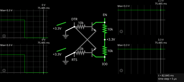
DTR and RTS are not directly connected to the chip. They are cross-connected to two transistors first.
The table below this part of the schematics indicates the behavior of this circuit as a logical gate. However, I find it mostly confusing. Considering DTR, RTS, EN and IO0 are all “active low”, it should not matter whether “0” (respectively “1”) mean electrical low or logical low, but it makes it harder to reason about. To avoid any ambiguity, I have made it fully explicit in the table below.
| Asserted | DTR | RTS | EN | IO0 | Function |
|---|---|---|---|---|---|
| Neither | 3.3 V | 3.3 V | 3.3 V | 3.3 V | Normal run |
| RTS & DTR | 0 V | 0 V | 3.3 V | 3.3 V | Normal run |
| RTS | 3.3 V | 0 V | 0 V | 3.3 V | Off |
| DTR | 0 V | 3.3 V | 3.3 V | 0 V | Bootloader |
If we look at the right column, we can see that we can still reset the chip and start it in normal mode or bootloader mode by selecting the right electrical levels for DTR and RTS. What changed is that the chip will run whether they are both high or both low. This tells us the purpose of this circuit: avoiding the automatic assertion of DTR and RTS from turning the chip off.
When we connected DTR and RTS directly to RST and GPIO0, opening the serial device would turn the chip off. We could turn it on again by de-asserting DTR (setting it to electrically high), but a reset was unavoidable.
With the two transistors in between, the chip will keep running even when we open the serial device. We can then choose to turn it off by de-asserting DTR. After that, we can start it again in normal mode or in bootloader mode as we want.
This is explained in the “Automatic Bootloader” section of the documentation.
Understanding the logical gate
To understand how these transistors achieve this, we can play around with the CircuitJS simulation below.
Both transistors in the circuit are “NPN transistors”:

They have three pins:
- B: the base, in the middle
- E: the emitter, on the side of the arrow
- C: the collector, on the other side
Simplifying slightly, when B is at higher electrical level than E (by 0.7V), E and C get connected together. When this happen, the transistor is said to be “saturated”.
Note: For a PNP transistor, the connection would happen when B is at a lower electrical level than E instead.
Looking at the top transistor (Q1, connected to EN), when DTR is electrically high and RTS is electrically low, B is electrically high and E is electrically low, so the transistor is saturated, connecting C to E. This causes C, and thus EN, to also be electrically low.
If we switch DTR to low and RTS to high, B is low and E is high, so E and C are not connected. To avoid leaving the electrical level of C (and thus EN) “floating”, it is connected to a resistor to 3.3V, making it default to electrically high. This is called a “pull-up” (if it were connected to 0V instead, it would be called a “pull-down”).
The opposite happens in the bottom transistor (Q2, connected to IO0).
We can also look at what happens if we flip the switches in the simulation.
First, let’s set DTR and RTS electrically low by flipping both switches to connect them to the ground. If you want to reproduce this, pause the simulation while you flip the switches.

This does not change the state of the output (the electrical level of EN and IO0). This is the main purpose of this circuit: opening the serial device does not change the state of EN, avoiding a forced reset.
Now, say we want to turn the board off. We switch DTR to electrically high:

The electrical level of EN flips to low, causing the board to turn off. IO0 is still electrically high, but this does matter since the board is off. If we flip DTR again, we go back to the previous situation, causing the board to start normally.
If we want to start in in bootloader mode, we flip both DTR and RTS, at the same time:

This causes EN and IO0 to both flip as well. Since EN is now electrically high, the board turns on. Since IO0 is electrically low, it starts in bootloader mode.
Conclusion
The reset mechanism of Arduino is pretty simple, but causes the board to reset whether the developer wants it or not. The mechanism used by Espressif is significantly harder to understand fully, but does provide a much nicer behavior for developers with full control from the host computer.
- Like we did in the article about DTR & RTS on Linux. ↩︎
- Strictly speaking, they are connected to the module. But you can check the schematics of the module itself (page 21 of the datasheet) and confirm that the TX/RX pins of the module are connected to those of the ESP32-S2 chip. ↩︎
- The resistors are 0Ω ones. This indicates that the goal is not to use an actual resistor, but to give an opportunity to users to easily modify the board. Here, this gives the option to disable the automatic reset behavior, if it is not wanted. For instance, if keeping IO0 electrically high or low interferes with some desired features. ↩︎
- Strictly speaking, they are connected to the module, here a ESP32-S2-WROVER-I. Inside the module, these pins are mapped to the corresponding pins of the actual ESP32-S2 microcontroller. Also note that Espressif’s documentation sometimes uses “EN”, for “ENable”, instead of “CHIP_PU”. ↩︎

Leave a Reply